- 您现在的位置:买卖IC网 > Sheet目录317 > CAT24C164YI-G (ON Semiconductor)IC EEPROM SERIAL 16KB I2C 8TSSOP
CAT24C164
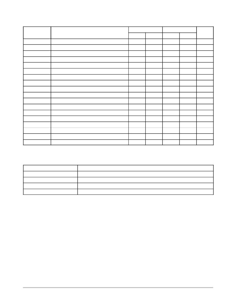
Table 5. A.C. CHARACTERISTICS (V CC = 1.8 V to 5.5 V, T A = ? 40 ° C to +85 ° C.) (Note 6)
Standard
Fast
Symbol
Parameter
Min
Max
Min
Max
Units
F SCL
t HD:STA
t LOW
t HIGH
t SU:STA
t HD:DAT
t SU:DAT
t R
t F (Note 7)
t SU:STO
t BUF
t AA
t DH
T i (Note 7)
t SU:WP
t HD:WP
t WR
t PU (Notes 7, 8)
Clock Frequency
START Condition Hold Time
Low Period of SCL Clock
High Period of SCL Clock
START Condition Setup Time
Data In Hold Time
Data In Setup Time
SDA and SCL Rise Time
SDA and SCL Fall Time
STOP Condition Setup Time
Bus Free Time Between STOP and START
SCL Low to Data Out Valid
Data Out Hold Time
Noise Pulse Filtered at SCL and SDA Inputs
WP Setup Time
WP Hold Time
Write Cycle Time
Power-up to Ready Mode
4
4.7
4
4.7
0
250
4
4.7
100
0
2.5
100
1000
300
3.5
100
5
1
0.6
1.3
0.6
0.6
0
100
0.6
1.3
100
0
2.5
400
300
300
0.9
100
5
1
kHz
m s
m s
m s
m s
m s
ns
ns
ns
m s
m s
m s
ns
ns
m s
m s
ms
ms
6.
7.
8.
Test conditions according to “A.C. Test Conditions” table.
Tested initially and after a design or process change that affects this parameter.
t PU is the delay between the time V CC is stable and the device is ready to accept commands.
Table 6. A.C. TEST CONDITIONS
Input Levels
Input Rise and Fall Times
Input Reference Levels
Output Reference Levels
Output Load
0.2 x V CC to 0.8 x V CC
≤ 50 ns
0.3 x V CC , 0.7 x V CC
0.5 x V CC
Current Source: I OL = 3 mA (V CC ≥ 2.5 V); I OL = 1 mA (V CC < 2.5 V); C L = 100 pF
http://onsemi.com
3
发布紧急采购,3分钟左右您将得到回复。
相关PDF资料
CAT24C208WI-GT3
IC EEPROM SER 8KB 400KHZ 8SOIC
CAT24C21LI
IC EEPROM SERIAL 1KB DUAL 8PDIP
CAT24C256XI-T2
IC EEPROM 256KBIT 400KHZ 8SOIC
CAT24C32HU3I-GT3
IC EEPROM 32KB I2C SERIAL 8UDFN
CAT24C32TSI-T3
IC EEPROM SRL 32KB I2C 5TSOP
CAT24C512HU5IGT3
IC EEPROM SRL 512KB I2C 8UDFN
CAT24C512XI
IC EEPROM I2C SRL 512KB 8SOIC
CAT24C64ZI-GT3
IC EEPROM I2C SRL 64KB 8MSOP
相关代理商/技术参数
CAT24C164YI-GT3
功能描述:电可擦除可编程只读存储器 16K-Bit Serial Cascadable RoHS:否 制造商:Atmel 存储容量:2 Kbit 组织:256 B x 8 数据保留:100 yr 最大时钟频率:1000 KHz 最大工作电流:6 uA 工作电源电压:1.7 V to 5.5 V 最大工作温度:+ 85 C 安装风格:SMD/SMT 封装 / 箱体:SOIC-8
CAT24C16C4ATR
功能描述:电可擦除可编程只读存储器 16KB I2C SER 电可擦除可编程只读存储器
RoHS:否 制造商:Atmel 存储容量:2 Kbit 组织:256 B x 8 数据保留:100 yr 最大时钟频率:1000 KHz 最大工作电流:6 uA 工作电源电压:1.7 V to 5.5 V 最大工作温度:+ 85 C 安装风格:SMD/SMT 封装 / 箱体:SOIC-8
CAT24C16C5ATR
功能描述:电可擦除可编程只读存储器 RoHS:否 制造商:Atmel 存储容量:2 Kbit 组织:256 B x 8 数据保留:100 yr 最大时钟频率:1000 KHz 最大工作电流:6 uA 工作电源电压:1.7 V to 5.5 V 最大工作温度:+ 85 C 安装风格:SMD/SMT 封装 / 箱体:SOIC-8
CAT24C16DWF
制造商:ON Semiconductor 功能描述:16KB I2C SER EEPROM - Rail/Tube
CAT24C16HU4I-GT3
功能描述:电可擦除可编程只读存储器 16KB I2C SER 电可擦除可编程只读存储器 RoHS:否 制造商:Atmel 存储容量:2 Kbit 组织:256 B x 8 数据保留:100 yr 最大时钟频率:1000 KHz 最大工作电流:6 uA 工作电源电压:1.7 V to 5.5 V 最大工作温度:+ 85 C 安装风格:SMD/SMT 封装 / 箱体:SOIC-8
CAT24C16HU4I-GT3JN
功能描述:IC EEPROM 16KBIT 400KHZ 8UDFN 制造商:on semiconductor 系列:- 包装:带卷(TR) 零件状态:有效 格式 - 存储器:EEPROMs - 串行 存储器类型:EEPROM 存储容量:16K(2K x 8) 速度:400kHz 接口:I2C,2 线串口 电压 - 电源:1.7 V ~ 5.5 V 工作温度:-40°C ~ 85°C(TA) 封装/外壳:8-UFDFN 裸露焊盘 供应商器件封装:8-UDFN-EP(2x3) 标准包装:3,000
CAT24C16LI
制造商:Rochester Electronics LLC 功能描述: 制造商:Catalyst Semiconductor 功能描述:
CAT24C16LI-G
功能描述:电可擦除可编程只读存储器 (2048x8) 16K 1.8-5.5 RoHS:否 制造商:Atmel 存储容量:2 Kbit 组织:256 B x 8 数据保留:100 yr 最大时钟频率:1000 KHz 最大工作电流:6 uA 工作电源电压:1.7 V to 5.5 V 最大工作温度:+ 85 C 安装风格:SMD/SMT 封装 / 箱体:SOIC-8
